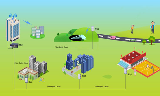


With the development of mobile communication technology, more and more new communication technologies(such as 4G) are being used nowadays. As a result, telecom operators have to run multiple systems simultaneously and provide multi-system services(2G/3G/4G) in one coverage area, resulting in the difficulty of installation and transmission of equipments. For the above mentioned reasons, Multi-Band Active DAS is designed to solve the problems of weak mobile signal in the place that is far away from the Base Transceiver Station(BTS) and has fiber optic cable network underground. The system consists of two parts: Master Unit and Remote Unit. The Master unit captures the BTS signal via direct coupler closed to BTS, then converts it into optic signal and transmits the amplified signal to the Remote Unit via fiber optic cable. The Remote unit will reconvert the optic signal into RF signal and provide the signal to the areas where network coverage is inadequate. And the mobile signal is also amplified and retransmitted to the BTS via the opposite direction.
Feature:
Application:
Diagram:

| Items | Master Unit | Remote Unit |
|---|---|---|
| LTE700 & LTE900 & LTE1800 & WCDMA2100 & LTE2600 | ||
| Frequency Range | Uplink | 703~748MHz&885~915MHz&1710~1775MHz&1920~1980MHz&2500~2570MHz |
| Downlink | 758~803MHz&930~960MHz&1805~1870MHz&2110~2170MHz&2620~2690MHz | |
| Transmission Distance | ≤20km | |
| Maximum Input Power (Non-Destructive) | 10dBm | |
| Maximum Output Power | 43±2dB per Band | |
| System Gain(MU+RU) | 55±3dB(MU+RU) | |
| Gain Adjustment Range | 0~30dB@Step of 1dB | |
| VSWR | ≤1.5 | |
| Noise Figure@1RU Connection | ≤5dB | |
| Gain Flatness | ≤±3dB | |
| Spurious Emission | 9kHz~1GHz: ≤ -36dBm/30kHz | |
| 1GHz~12.75GHz: ≤ -30dBm/30kHz | ||
| System Delay | ≤5us | |
| I/O Impedance | 50Ω | |
| RF Connector | 5 X N-Female for MU,DIN-Female for RU | |
| Optical Connector | 4 X FC/APC for MU,1 X LC/UPC for RU | |
| Fiber Type/Number | Single mode | |
| Optical Output Power | 0±3dBm@1310nm/≥±3dBm@1550nm | |
| Optical Receiver Sensitivity | ≥-15dBm | |
| Temperature Range | -25°C ~ + 55°C | |
| Relative Humidity Range | ≤95%(non condensing) | |
| Power Supply(Customized) | AC100-240V,50/60Hz | |
| Dimensions | 483x223x500 mm | 980x420x230 mm |
| Weight | ≤10kg | ≤50kg |
| Aplication | Indoor(IP30) | Indoor or Outdoor(IP65) |
| Local Control | Web Browser GUI Local Via RJ-45 Interface or WiFi Hotspot | |
| NMS Mode(Optional) | Wireless Modem (3G/4G), IP Connectivity | |
| NMS Function(Optional) | Real-time alarm for door status, temperature, power supply, VSWR, etc; Remote control such as turn on/off, increasing/decreasing output power etc; Real-time status for output/input power, UL/DL gain, all status of Active DAS etc. | |
DAS is Distributed Antenna System, by using RF directional couplers and (or) wireless amplifiers to split and amplify the wireless signal from the source out to the distributed antennas. DAS consists of several antennas as opposed to one to provide wireless coverage to the same area with reduced total power and additional reliability.
Active DAS is a kind of device that design to solve the problems of weak mobile signal in the place where is far away from the Base Transceiver Station (BTS) and has fiber optic cable network underground. It can run multiple systems simultaneously and provide multi-system services (2G/3G/4G) in one coverage area.
Active DAS consists of two parts: Master Unit and Remote Unit. The Master unit captures the BTS signal via direct coupler close to BTS, then converts it into optic signal and transmits the amplified signal to the Remote Unit via fiber optic cable. The Remote unit will reconvert the optic signal into RF signal and provide the signal to the areas where network coverage is inadequate. On the other hand, the mobile signal is also amplified and retransmitted to the BTS via the opposite direction.